Ron Fredericks writes: recently I discovered that I was going to have to create my own IC component and symbol for my on-going digital volume control circuit simulation. My first step was to check in with the LTspice forum on yahoo groups. On the forum I requested any previous design for the IC I needed. I also asked the group’s readership if they thought it was correct to build a new IC from existing low level digital gates – gates that are already supplied with the LTspice distribution by Linear Technologies.
Well, I did not find a previous inventor for my IC simulation, but I did get confirmation that the gate build-up was a common strategy. And, this same forum engineer supplied me with a copy of an IC simulation of his own – one very similar to my IC requirement – he supplied a symbol and sample test bed to accelerate my learning curve. Here is a link to my support dialog.
I would like to thank Helmut Sennewald for his time and excellent service to the LTspice yahoo forum. It is his effort and many others who make this forum such a valuable community resource. This forum in turn, has made the LTspice/SwitcherCAD III circuit capture and spice tool a viable design tool for many embedded component users and EE designers.
Introducing the T S-R Flip-Flop
To build my new IC, I had to build a new digital logic block. This component is a Toggle Flip-Flop with Set and Reset functions added. In this blog post I introduce my readers to this new component and share the simulation circuit for others to use and learn from.
See the figure below for an initial design of the T S-R Flip-Flop, including a truth table in the form of a waveform diagram, the circuit, a pulse detector sub-circuit and their related assemblies. This circuit is just an initial design because it uses an S-R Flip-Flop and a simple pulse detector sub-circuit for its clock.
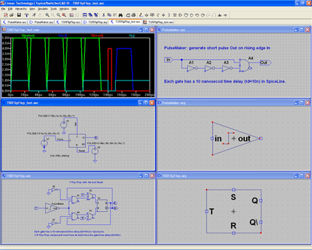
View larger image>
Final Design for the T S-R Flip-Flop
This section of my post is an update, thanks to a review by Helmut Sennewald. See figure below for my final design of the Toggle S-R Flip-Flop. This design overcomes two problems in my initial design, both resolved by starting with the D Flip-Flop with its built-in clock. The reuse of this more full-featured LT supplied component in my design eliminated the home-brew pulse maker sub-circuit. And in so doing, the slower S-R Flip-Flop. Slower because I had to set the SpiceLine time delay to a minimum of 20 nanoseconds (or td >= 2x the gate time delay) to support the simulation of my simple pulse maker sub-circuit. The D Flip-Flop has an internal clock so I could eliminate the pulse maker sub-circuit. End result: one less sub-circuit and faster Flip-Flop simulation using a time delay set to a minimum of 10 nanoseconds (or td >= 1x the gate time delay).
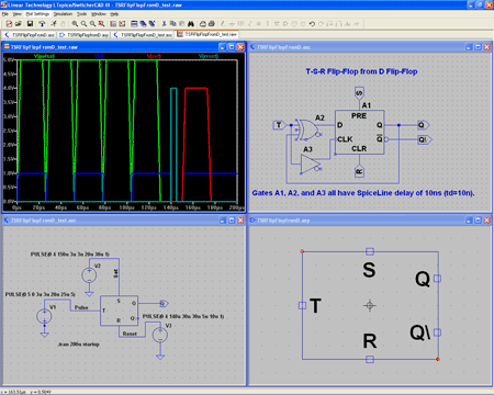
View larger image>
Download
To test my knowledge of digital design using the LTspice tool, I created a number of similar flip-flop components which are included in the download:
- S-R Flip-Flop test circuit
- S-R Flip-Flop with Enable gate and test circuit
- S-R Flip-Flop with rising edge clock and test circuit
- J-K Flip-Flop with rising edge clock and test circuit
- D Flip-Flop with Enable gate and test circuit
- T S-R Flip-Flop from S-R Flip-Flop and test circuit (initial design)
- Rising Edge Pulse Detector (not high performance design)
- T S-R Flip-Flop from D Flip-Flop and test circuit (final design)
Download the components listed above for your LTspice designs all in one zipped directory.
Technorati Tags: Ron Fredericks, component, circuit, simulation, LTspice, Linear Technologies, Helmut Sennewald, embedded